Simple Hardware Hacking: Auto "On Air" VC Indicator - Chapter 3
If this is the first post in this series you're landing on, I recommend checking out Chapter 1 and Chapter 2 as we'll be building on the groundwork that those posts laid.
In this post we're going to cover:
Working with Arduino
Using Adafruit NeoPixels
Simple Serial Communication
Overview
After our last blog post, we had something that was technically working, but our "Sign" left something to be desired.
The main problems that our current solution suffers from are:
mounting
The existing system requires that I somehow affix my unwieldy RaspberryPi to the wall so it’s decently visible
fragility
While the breadboard was okay for prototyping, it wasn't exactly a paragon of resilience. Any solution should be at least somewhat robust.
style
Admittedly, lower down than the other two but any solution should be a step up in the looks department over the single red LED we were working with before.
To be straightforward with you, many of the decisions in this project were guided by the desire to use what I already had instead of buying components specifically for this project. There's no reason why we couldn't enhance the circuit we used in part one and come up with something that worked as well as or even better than what I'm proposing. In this case, though, the lowest friction solution to the problems above were to delegate the responsibility of actually displaying the status to another device. To be clear, we're alright with using the RaspberryPi but it would be great if we could have some other component that the RaspberryPi can control.
Luckily, I just happened to have something that addresses all of these things.
Adafruit Circuit Playground (Bluefruit Edition)
Sometimes signing up for random subscription boxes can have their perks. For a while, I was subscribed to the AdaBox. As a result, I had a Circuit Playground BlueFruit and case literally lying around which looked like a perfect candidate for the job:
It's quite a bit smaller than the raspberry pi (once you take into account the case) which will make it easier to mount.
It has its own case that should protect it much better than just having bare wires hanging out on the floor.
It has 10 RGB NeoPixels that we can independently control which will allow us to have all manner of exciting displays.
We can connect it via USB to the RaspberryPi which will provide us with power and data.
Okay, so we have our new candidate for our "Notifier". Let's start getting it to do something interesting.
Setting up the Arduino IDE
In order to set up the Arduino IDE check out the official Circuit Playground Bluefruit Arduino IDE setup guide to get started. This guide will tell you how to install the IDE and get the IDE to recognize your board.
Once you've completed that, we need to install the library that we'll be using to control the NeoPixels on our Bluefruit.
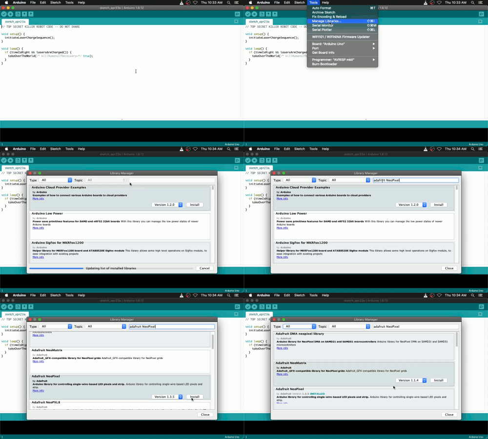
From the top menu select Tools > Manage Libraries ...
A very similar dialog to the board manager will appear. In the search bar here, we can search NeoPixel. There may be a few libraries that match. We're using the library called "Adafruit NeoPixel"
As before, click "Install" from the corner of the NeoPixel library box.
Once that's installed, you can close the dialog.
And that's it! We should be ready to start hacking with the NeoPixels on our Bluefruit!
Getting the NeoPixels Working
As always, let's start from something simple and work our way up to something more interesting. We'll start by turning one of the neopixels on. Enter the following code into the IDE
#include <Adafruit_NeoPixel.h>

#define PIN 8
#define NUMPIXELS 10

Adafruit_NeoPixel pixels(NUMPIXELS, PIN, NEO_GRB + NEO_KHZ800);

// the setup function runs once when you press reset or power the board
void setup() {
  pixels.begin();  // INITIALIZE NeoPixel strip object (REQUIRED)
  // pixels.Color() takes RGB values, from 0,0,0 up to 255,255,255
  // Here we're using a moderately bright red color:
  pixels.setPixelColor(0, pixels.Color(100,0,0));

  pixels.show();  // Send the updated pixel colors to the hardware.
}

// this is necessary even though we're not doing anything with it yet
void loop() {
}
Now we'll have to send this to our board. To do this, click the "Upload" button in the main menu bar of the IDE.
Once it finishes programming, one of your NeoPixels should turn on. Feel free to play around and change the values of the color object or which pixel you turn on. Whenever you change the code, you'll need to click the upload button again for your changes to take effect.
Let's try something slightly more exciting. Let's turn all the lights on in succession. Here's the code to do that:
#include <Adafruit_NeoPixel.h> #define PIN 8 #define NUMPIXELS 10 #define DELAYVAL 200 // Time (in milliseconds) to pause between pixels Adafruit_NeoPixel pixels(NUMPIXELS, PIN, NEO_GRB + NEO_KHZ800); void setup() { pixels.begin();for (int i = 0; i < NUMPIXELS; i += 1) { // For each pixel... pixels.setPixelColor(i, pixels.Color(0,100,0)); pixels.show(); // Send the updated pixel colors to the hardware. delay(DELAYVAL); // Pause before next pass through loop }} void loop() { }
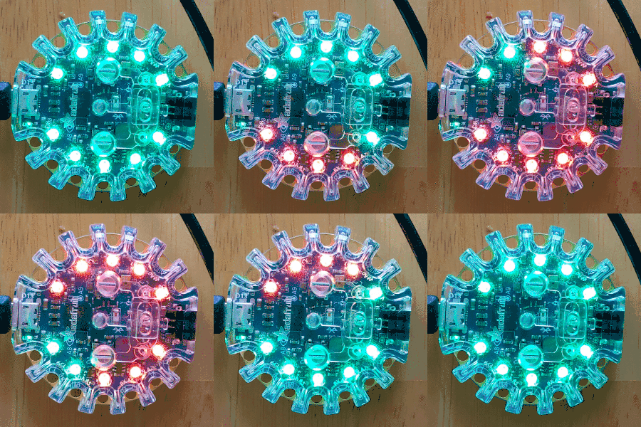
We've introduced a new DELAYVAL variable which controls how quickly the lights in the ring light up and then we loop through the number of pixels that we have, turning each on in series.
When you upload this version, your pixels should do a nice dance for you :) For our purposes, that will be enough complexity in our NeoPixel code. The next challenge is to send commands to the Bluefruit to turn on or off or change colors.
Reading From Serial Input
So we want to receive commands. To do that we'll be using serial communication. In our case, that's just another name for receiving information over USB (it does stand for Universal Serial Bus after all!)
#include <Adafruit_NeoPixel.h> #define PIN 8 #define NUMPIXELS 10 #define DELAYVAL 200 Adafruit_NeoPixel pixels(NUMPIXELS, PIN, NEO_GRB + NEO_KHZ800); void setup() {// 9600 here defines how quickly the devices are communicating Serial.begin(9600);pixels.begin(); } void setColor(uint32_t color) { for (int i = 0; i < NUMPIXELS; i += 1) { pixels.setPixelColor(i, color); pixels.show(); delay(DELAYVAL); } } void loop() {if (Serial.available() > 0) { // Read one character from the serial connection (USB) char receivedChar = Serial.read(); uint32_t newColor; // IMPORTANT! Make sure you use single quotes here! if (receivedChar == 'y') { setColor(pixels.Color(100,0,0)); // set pixels to red } else if (receivedChar == 'n') { setColor(pixels.Color(0,100,0)); // set pixels to green } }}
Important! make sure to use single quotes around the y and the n in the comparison to receivedChar. They are different things in C. If you use double quotes it will assume it's a string literal, if you use single quotes it will think it's a character.
Note: It may seem counterintuitive that a command of y makes the pixels red and vice versa but this character indicates whether the person is "busy" so yes busy translates into red meaning stop.
So now we've got some stuff in our loop method. It's constantly waiting for input. If it sees a 'y' or 'n', it will update the pixels, otherwise it doesn't worry too much about it.
If you upload this you'll notice that it doesn't do anything very interesting. Well, that's because we're not telling it to do anything interesting! Now, we need to send it commands. Since we're planning on controlling it from our Python Flask server, we'll start by sending it commands from the Python REPL.
Before we get started though, you guessed it! We'll need to install the required dependencies!
$ sudo pip3 install pyserial
Once you've installed that you can fire up the Python REPL by entering python3 into a terminal or powershell window. Once you're there, enter the following commands:
>>> from serial import Serial
>>> ser = Serial("COM3", 9600) # confirm which COM port you're using in the Arduino IDE before entering this, otherwise this connection will probably fail, if you're on a *nix flavor it'll look something like /dev/ttyACM1
>>> ser.write('n'.encode('utf-8')) # write accepts raw bytes so we need to encode them from a string to the bytes representation.
>>> ser.write('y'.encode('utf-8'))
If everything's set up correctly, you should see your Bluefruit spring to life! As you submit new requests, your bluefruit should respond accordingly.
Updating our Flask Server
It's been a while but here was the main thrust of our original server. We actually shouldn't need to change much:
from flask import Flask
from gpiozero import LED

app = Flask(__name__)
led = LED(YOUR_GPIO_PIN)

@app.route('/on')
def on():
  led.on()
  return 'Turned LED on successfully!'

@app.route('/off')
def off():
  led.off()
  return 'Turned LED off successfully!'
Mostly, we just need a send method to send a message to our Bluefruit. Let's give that a shot:
from flask import Flask from serial import Serial, SerialException from serial.tools.list_ports import comports app = Flask(__name__)def send(msg): connected_devices = comports() for device in connected_devices: if device.manufacturer == ADAFRUIT_MANUFACTURER: ser = Serial(device.device, 9600, write_timeout=5) ser.write(msg.encode('utf-8')) ser.close()@app.route('/on') def on(): send('y') return 'Turned LED on successfully!' @app.route('/off') def off(): send('n') return 'Turned LED off successfully!' app.run(host='0.0.0.0')
To explain what’s going on here: We're using the comports utility to get the list of connected usb devices, next we check for the one that we're trying to connect to. We use the manufacturer to tell whether or not we should attempt to connect. Once we find the device we're interested in, we create a serial connection to it, send the requested message then close the connection.
Pretty straight forward.
You may be thinking, huh that seems kind of wasteful to create a connection every time a request comes in. If this server were getting many requests per second, it may be worthwhile to maintain an open connection. In our case though, this server is getting O(10s) of queries a day so we're not too worried about a bit of additional latency on each request. But this makes sure that we're robust to connections going stale and the device getting unplugged and replugged in.
Conclusion
So our little one day project is really turning into something. Now we've got a lovely RGB pixel delay with a nice animation between states!
Communicating when we're in meetings is nice, but that's obviously not the only reason you might not be disturbed. Stay tuned for future posts where we try to detect if we're napping!
References:
https://github.com/AlabasterAxe/meeting_status_indicator/blob/master/arduino/Blink/Blink.ino

